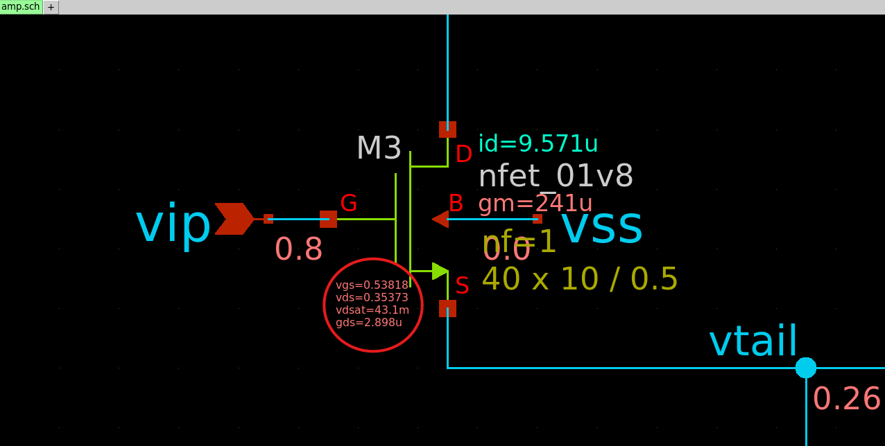
DC Operating Point Annotation on SKY130A and xschem
A large majority of analog design time takes place with the DC operating point analysis. Once the bias points for a circuit have been established correctly, it becomes largely trivial to get it to the desired performance. Observing the steady-state node voltages and the operating points of transistors via their small-signal parameters gives complete
The SKY130A open-source analog flow, with ngspice and xschem, supports DC annotations. However, I’ve found that these are largely limited to node voltages, which can be somewhat limiting. A few additional steps are required to get complete information about the operating points of transistors and here I’ll try to explain how to complete the picture.
Saving MOS Transistor Operating Points
In the SKY130A PDK, MOS transistors are defined as macromodels: parametrizable subcircuits that instantiate the actual transistor device internally. This approach seems to have been chosen to enable automatic model selection via width/length and also to conduct parameter calculations (mainly related to mismatch). A typical model definition looks like the following:
*  Nmos Model
.subckt  sky130_fd_pr__nfet_01v8  d g s b  mult=1
.param  l = 1 w = 1 nf = 1 ad = 0 as = 0 ...
Msky130_fd_pr__nfet_01v8  d g s b nshort_model l = {l} w = {w} ad = {ad} as = {as} ...

.model nshort_model.1 nmos
+ level = 54 lmin = 8E-6 lmax = 2.02E-5 wmin = 7E-5
+ wmax = 1.01E-3 version = 4.5
...

.model nshort_model.2 nmos
+ level = 54 lmin = 4E-6 lmax = 8E-6 wmin = 7E-6
+ wmax = 1.01E-3 version = 4.5
...

.ends sky130_fd_pr__nfet_01v8
Here the line .subckt sky130_fd_pr__nfet_01v8 d g s b mult=1 ... defines the subcircuit for the transistor and the line Msky130_fd_pr__nfet_01v8 d g s b nshort_model l = {l} w = {w} ... defines the transistor instantiation itself. What follows are numbered model definitions starting with .model nshort_model.1 nmos and featuring the lmin, lmax, wmin, wmax parameters to define the geometry range the model is valid for.
When this device is netlisted through xschem, it will express that it is a subcircuit instantiation by prefixing it with an X. A typical device instantiation will look like:
XM3 von vip vtail vss sky130_fd_pr__nfet_01v8 L=0.5 W=10 nf=1 ...
ngspice does not save the evaluated operating point information for these models (such as id, gm, vdsat) by default. It has to be instructed to save these parameters if you want to annotate them. This is achieved by a save command in the netlist:
.save @m.XDUT.XM3.msky130_fd_pr__nfet_01v8[id]
.save @m.XDUT.XM3.msky130_fd_pr__nfet_01v8[gm]
...
The format of the save command generally follows: .save @m.{path}.msky130_fd_pr__{model}[{param}]. Here {path} refers to the full path to the device subcircuit. In the above example, the device is XM3 which is in an amplifier XDUT, so the full path is XDUT.XM3. The {model} refers to the actual model of the device, and in the example, it is nfet_01v8. Generally, the model name is printed on the symbol in xschem. Finally, {param} is the operating point information to be saved.
When the netlist is run with these save commands, running a print all command will reveal that the operating point information is saved for the device:
ngspice 533 -> print all
...
@m.xdut.xm3.msky130_fd_pr__nfet_01v8[id] = 9.579547e-6
@m.xdut.xm3.msky130_fd_pr__nfet_01v8[gm] = 2.409997e-4
...
Automating .save Commands
It can get quite unwieldy to write .save commands for a large number of devices. A simple Python script makes it easy to generate all the save commands for all transistors in a netlist. It reads in a .spice netlist file and generates a .save file that has all the save commands for all devices and the specified parameters.
block = 'amp'
testbench = 'dc'
subcircuit = 'xdut'
params = ['id', 'gm', 'gds', 'vdsat', 'vth']

fname_spice = f'{block}/simulation/tb_{block}_{testbench}.spice'
fname_save = f'{block}/simulation/tb_{block}_{testbench}.save'

with open(fname_spice, 'r') as f_spice:
    with open(fname_save, 'w') as f_save:
        lines = f_spice.readlines()

        for i, line in enumerate(lines):
            if line.startswith('XM'):
                tokens = line.split()
                name = tokens[0]
                model = tokens[5]

                for param in params:
                    f_save.write(f'.save @m.{subcircuit}.{name}'
                                 f'.m{model}[{param}]\n')
Unfortunately, this script is quite limited in scope. It only works for transistors instantiated within a single subcircuit (named via the subcircuit = 'xdut') line. A more generic version could traverse the entire SPICE netlist, build a tree out of all the subcircuit instantiations and populate the .save file.
Finally, this .save file can be included in your netlist via an .include tb_{block}_{testbench}.save command, keeping the actual netlist definition uncluttered.
DC Operating Point Annotation in xschem
Default symbols for SKY130A devices in xschem already come with text boxes that annotate some parameters like id, gm, vds and vgs. These are quite useful ss it is but an extension with some additional small-signal parameters gives more complete information about the device’s operating condition.
This can be achieved by editing the device symbol file through xschem (even though you’ll need write permissions to the pdk area) or directly editing the text file under $PDK_ROOT/$PDK/libs.tech/xschem/sky130_fd_pr/{device}.sym. These symbols will already have some examples that can be extended, but the general format for the contents of a text box looks like this:
tcleval(vgs=[to_eng \{@#1:spice_get_voltage - @#2:spice_get_voltage \}]
vds=[to_eng \{@#0:spice_get_voltage - @#2:spice_get_voltage \}]
vdsat=[to_eng [ngspice::get_node v(\\@m.$\{path\}@spiceprefix@name\\.msky130_fd_pr__@model\\\\\\[vdsat\\\\])]]
gds=[to_eng [ngspice::get_node \\@m.$\{path\}@spiceprefix@name\\.msky130_fd_pr__@model\\\\\\[gds\\\\]]] )
When the schematic is annotated, these boxes get evaluated and pull the operating point information saved in the raw file. This setup looks like this in xschem, and is what I currently use:
